
Many motion control applications use permanent magnet DC motors because, compared with AC motors, their control systems are easier to implement. For this reason, DC motors are commonly chosen when speed, torque, or position control is required.
There are two main types of DC motors in common use: brushed DC motors and brushless DC motors, also known as BLDC motors. As the name suggests, brushed DC motors use brushes to switch the motor current and maintain rotation, whereas brushless motors replace mechanical commutation with electronic control.
Many applications can use either brushed or brushless DC motors. Both types operate on the same principle of attraction and repulsion between wound coils and permanent magnets, and each has its own advantages and disadvantages, allowing selection based on specific application requirements.
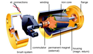
DC motors use wound coils to generate magnetic fields. In brushed motors, the coils rotate freely to drive the shaft and are referred to as the rotor. The coils are typically wound around an iron core, although there are also coreless brushed motors in which the windings are self-supporting.
The stationary part of the motor is called the stator. Permanent magnets that provide a fixed magnetic field are usually mounted on the inner surface of the stator and around the exterior of the rotor.
To produce torque that rotates the rotor, the magnetic field of the rotor must rotate continuously so that it attracts and repels the fixed magnetic field of the stator. This rotating field is typically achieved using a sliding electrical switch consisting of a commutator and fixed brushes. The commutator is usually a segmented contact assembly mounted on the rotor, while the fixed brushes are attached to the stator.
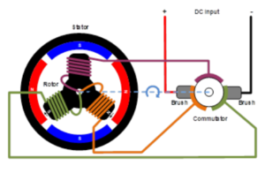
As the rotor turns, the commutator repeatedly connects and disconnects different rotor windings, causing the rotor coils to be continuously attracted and repelled by the fixed magnets of the stator, thereby maintaining rotation.
Mechanical friction occurs between the brushes and commutator in brushed motors, and since these are electrical contacts, lubrication is generally not possible. As a result, brushes and commutators experience mechanical wear over the motor’s service life, which can eventually lead to failure. However, many brushed motors, especially larger ones, feature replaceable brushes, typically made of carbon, which maintain good contact even as they wear. These motors require periodic maintenance. Even with replaceable brushes, the commutator will eventually wear to the point where the motor must be replaced.
Driving a brushed motor requires applying a DC voltage across the brushes, allowing current to flow through the rotor windings and produce rotation.
If a brushed motor only needs to rotate in one direction without speed or torque control, no drive electronics are required at all. In such applications, the motor can simply be started or stopped by switching the DC voltage on or off, which is common in low-cost applications such as electric toys. Reversing rotation can be achieved using a bipolar switch.
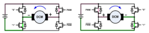
When speed, torque, and direction control are needed, an H-bridge composed of electronic switches — transistors, IGBTs, or MOSFETs — is used to drive the motor in either direction. Voltage of either polarity can be applied to the motor, causing it to rotate in different directions. Motor speed or torque can then be controlled by modulating the width of the switching pulses.
Brushless DC Motors
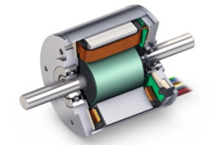
Brushless DC motors operate on the same magnetic attraction and repulsion principles as brushed motors but differ slightly in construction. Instead of mechanical commutators and brushes, brushless motors use an electronic commutator to rotate the stator magnetic field, which requires active control electronics.
In a brushless motor, permanent magnets are attached to the rotor, while windings are mounted on the stator. The rotor can be positioned inside the windings, as shown in the diagram above, or outside the windings, sometimes referred to as an outer-rotor motor.
The number of windings used in a brushless motor is called the number of phases. While different phase configurations exist, three-phase brushless motors are the most common. Smaller applications such as cooling fans may use single‑phase or two‑phase designs.
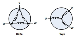
The three windings of a brushless motor are typically connected in either star (Y) or delta (Δ) configuration. In both cases, three wires connect to the motor, and the drive techniques and waveforms remain the same.
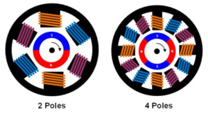
Three‑phase motors can be built with different magnetic configurations known as pole pairs. The simplest three‑phase motor has two poles, meaning the rotor has a single pair of magnetic poles: one north and one south. More poles can be implemented by adding additional magnetic sections in the rotor and extra windings in the stator. Higher pole counts improve performance, while lower pole counts enable higher rotational speeds.
To drive a three‑phase brushless motor, each of the three phase windings must be switched to either a high or low potential in sequence according to the rotor position. This is typically accomplished using three half‑bridge drive circuits, each consisting of two switches. Depending on the required voltage and current, these switches may be bipolar transistors, IGBTs, or MOSFETs.
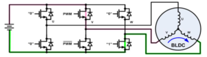
Several drive techniques are available for three‑phase brushless motors. The simplest is known as trapezoidal drive, square‑wave drive, or 120‑degree commutation control. Trapezoidal commutation is somewhat similar to commutation in brushed DC motors: at any given time, one phase is connected to ground, one phase is open, and the third phase is connected to the supply voltage. Speed or torque control is achieved by pulse‑width modulating the phase connected to the supply voltage. Because phases switch abruptly at each commutation point while the rotor rotates continuously, torque varies as the motor turns, a phenomenon known as torque ripple.
Improved performance can be achieved using alternative commutation methods, such as sinusoidal or 180‑degree commutation, in which all three motor phases are driven continuously. The controller regulates the drive to produce sinusoidal currents in each of the three phases, with a 120‑degree phase shift between them. This drive technique minimizes torque ripple, noise, and vibration, making it suitable for high‑performance or high‑efficiency drives.
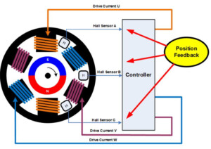
To properly rotate the magnetic field, the control electronics require knowledge of the physical position of the rotor magnets relative to the stator. This position information is typically obtained using Hall sensors mounted on the stator. As the magnetic rotor turns, the Hall sensors detect its magnetic field. The drive electronics use this information to sequence current through the stator windings and maintain rotor rotation.
Using three Hall sensors, trapezoidal commutation can be implemented with simple combinational logic, eliminating the need for complex control electronics. Other commutation methods, such as sinusoidal commutation, require more sophisticated electronics and usually a microcontroller.
Besides using Hall sensors for position feedback, several methods can determine rotor position without sensors. The simplest approach involves monitoring the back EMF on the undriven phase to sense the magnetic field relative to the stator. A more advanced control algorithm, known as Field-Oriented Control (FOC), calculates position based on rotor current and other parameters. FOC typically requires a powerful processor to perform numerous calculations rapidly, making it significantly more expensive than simple trapezoidal control.
Service Life
As previously noted, a major drawback of brushed motors is mechanical wear between the brushes and commutator. Carbon brushes, in particular, are consumable items and require periodic replacement in many motor maintenance schedules. The soft copper of the commutator also gradually wears away due to brush contact, eventually leading to motor failure. Brushless motors have no moving contacts and therefore experience no such wear.
Speed and Acceleration
The speed of brushed motors is limited by the brushes, commutator, and rotor mass. At very high speeds, contact between brushes and commutator becomes unstable, and arcing across the brushes increases. Most brushed motors also use laminated iron cores in the rotor, resulting in relatively high moment of inertia, which limits acceleration and deceleration rates. Using high‑performance rare‑earth magnets in the rotor can minimize moment of inertia, though at increased cost.
Electrical Noise
Brushes and the commutator act as electrical switches. As the motor rotates, these switches open and close, causing large currents to flow through the inductive rotor windings and producing arcing at the contacts. This arcing generates significant electrical noise that can couple into sensitive circuits. Adding capacitors or RC snubbers across the brushes can reduce arcing to some extent, but the instantaneous switching of the commutator still produces some electrical noise.
Acoustic Noise
Brushed motors use “hard switching,” meaning current is abruptly transferred from one winding to another. As windings are switched on and off, torque varies during rotor rotation, creating torque ripple. Brushless motors can control winding current to transition gradually between phases, reducing torque ripple. Torque ripple represents mechanical pulsation of energy on the rotor, causing vibration and acoustic noise, especially at low rotor speeds.
Cost
Brushed motor technology is well‑established and inexpensive to manufacture. Brushless motors require more complex electronics, resulting in higher overall system cost, but are mechanically simpler to produce without brushes and commutators. Brushless motors have become increasingly widespread, especially in high‑volume applications such as automotive motors. Furthermore, falling costs of electronic components such as microcontrollers have made brushless motors more economically attractive.
Conclusion
Brushless motors have grown increasingly popular due to declining costs and superior performance. However, brushed motors remain the best choice for certain applications.
As seen in automotive applications, by 2020 most continuously operating motors in vehicles, such as pumps and fans, had transitioned from brushed to brushless designs to improve reliability. Reduced field failure rates and lower maintenance requirements have fully offset the higher cost of brushless motors and their drive electronics.
On the other hand, motors used for infrequent operation, such as those for power seats and power windows, still predominantly use brushed designs. Total operating time over the vehicle’s lifetime is relatively short, making failure unlikely.
As costs of brushless motors and associated electronics continue to decrease, brushless designs are gradually penetrating applications traditionally dominated by brushed motors. Another automotive example is the use of brushless motors in seat adjustment systems in high‑end vehicles, primarily due to their lower acoustic noise.